Reverse Engineering Capabilities

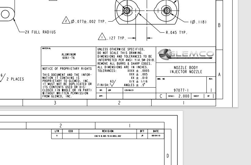
Reverse Engineering involves taking existing physical parts and assemblies and creating CAD models and detail drawings that provide correct tolerances. The data that is collected and CAD modeled, can be used to troubleshoot, reproduce, study, analyze, inspect, or can be applied to other future applications or product enhancements. 3D CAD models can be easily updated for changes in the product design and/or tool or die design.
Understanding the function of the component or assembly is paramount to the reverse engineering process. It is not enough to duplicate a physical part into CAD space, but you must know how the part/assembly interacts with surrounding components in the overall system. This will allow the proper tolerance stacking information that is needed to reproduce the part. Our process continues by gathering all existing information, including pertinent information from our customer regarding desired use and function, and digitizing provided sample parts.
Once data is collected, we create CAD models using Creo. These models are verified against the original physical part. This gives us the confidence that our CAD models match the physical part. These models form the basis for creating detailed drawings with precise measurements used during manufacturing. Knowledge of the end-use application gives us the basis for establishing datum reference frames, and in the process of comprehensive modeling and tolerancing.
By translating complex physical shapes into digital models by reverse engineering you can create CAD models to design and develop tooling for manufacturing processes, easily make design changes in part, tool or mold, and interchange CAD files with other CAD systems, product and designers, contract manufacturers, etc.
Since 1978
We are proud to support our local communities with jobs that offer good working environment, excellent pay and benefits, growth opportunities and stability. Proud to be an American Manufacturer and a Woman Owned Business.
Contact Us Today